Proof of Concept #7 - Dayton PA310 TL
23 January 2025
*** IN PROGRESS ***
For this particular "proof of concept", I opted to try and build a "straight" TL for a driver that I already have on hand and am familar with, the Dayton PA310. The 50 Hz MLTL that I'd previously built for it was going unused, and wanted to prove a few hypotheses that I had about TL design, so pulled the driver from that build to use it in this one.
A straight TL (i.e. no taper along its path) offers a number of advantages for subwoofer duty. The mouth is fairly large, so vent compression effects at high SPL levels should be very small, and likely not noticeable. Construction should also be very simple, as all bends are going to be right-angled bends. It's also pretty easy to increase the output around Fb by simply upsizing the TL while keeping the path length constant.
Unfortunately straight TLs also have some disadvantages, the primary one being that the harmonic resonance frequencies are now much closer to the primary resonance frequency of the design, and this could impact its useful bandwidth. For this reason I wouldn't recommend a straight TL design for full-range duty unless you were planning to heavily damp the line, at which point you'll be significantly reducing the output at Fb as well. For subwoofer duty though, the reduced usable bandwidth shouldn't cause too much of an issue because subwoofers usually operate over a limited bandwidth anyway.
Finally, this is a TL, so that pesky first harmonic resonance needs to be dealt with, as it would cause a huge notch in the combined response and as is this a straight TL, that notch is going to end up being a lot closer to the Fb of the design than if the TL was tapered.
This particular design uses a fold for the TL that results in the driver being positioned very close to the optimum location to null out the first harmonic resonance. The driver also ends up being positioned very close to the vent, which means that the summed response will only start deviating from the predicted response curve at high frequencies.
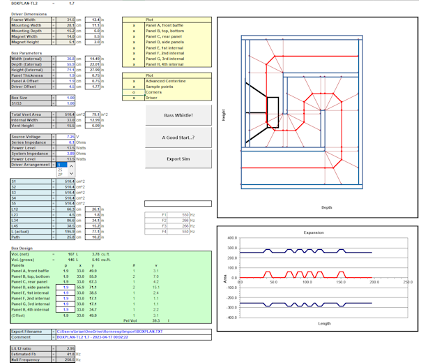
Below is the BOXPLAN that I put together for this particular build.
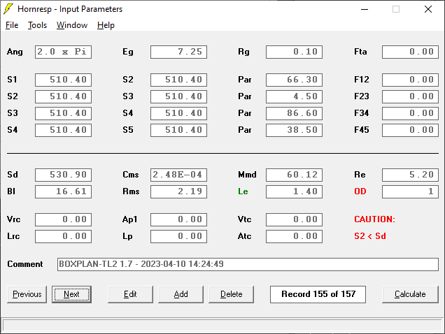
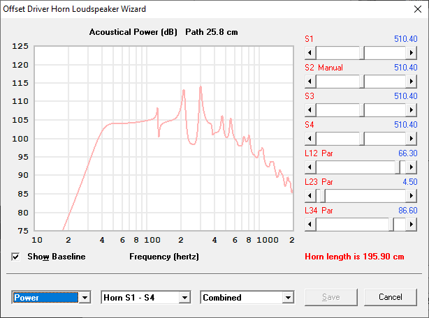
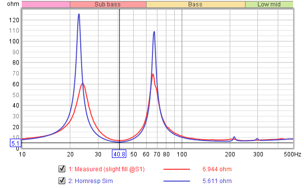
...and the corresponding Hornresp sim:
Build Pictures
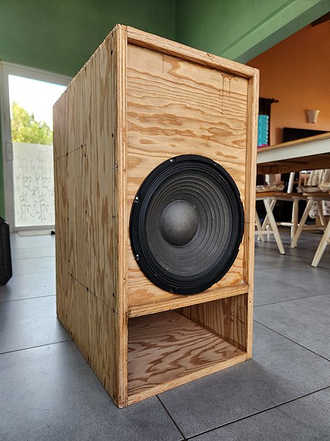
This is the first POC design that I actually didn't build myself, so I only have a picture of what it looks like after it was built. Here it is before I've done any finishing work on the build.
Results
A measured impedance curve of the Dayton PA310 mounted in the POC7 enclosure showed an impedance dip at almost exactly where Hornresp predicted it would be, suggesting that the build was a pretty good match for the Hornresp sim. As for how it sounded, at first I wasn't all that impressed, I thought that the subwoofer sounded a bit coloured, but adding some stuffing in the first section of the line improved things quite a bit. With just a simple 12dB/oct lowpass filter at 100 Hz (provided by the Technics receiver that I was using for testing purposes) the integration with one of the Blastomara speakers that I was using for testing testing purposes was almost perfect.
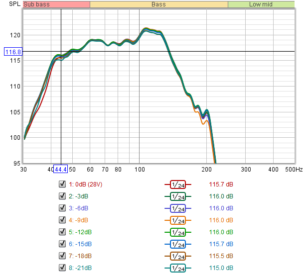
Below is some measurements I took to determine the system's linearity, by measuring its response at various signal levels up to 100W, where the THD in the passband was starting to exceed 10%, around the same level that Hornresp predicted that it would happen. Note that this graph should not be considered as a frequency response graph, as it was taken in my garage and the response would be impacted by nearby walls.
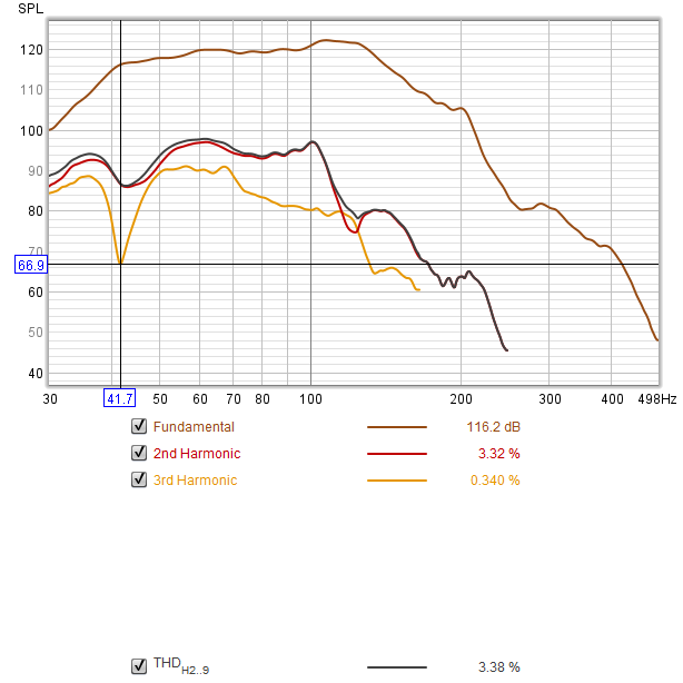
The distortion profile of this build is a bit unusual, and I'm not sure what to make of it yet. The odd order distortion looks a lot like what I expect it to look like, with a reduction near Fb and an increase in the passband where the driver's excursion is at its highest. However the even order distortion is a bit higher than I expected it to be, and I'm not sure of the cause yet (Update: I subsequently found out that the driver that I used for the test was suffering from a bit of "cone sag", which resulted in the higher than expected 2nd order distortion). The image below shows the THD at -6dB below maximum linearity test level.
Below is a comparison of the output of POC7 with POC3 using the same driver, measured under identical conditions. While the POC3 tapped horn has 1~2 dB more output between 42 Hz and 88 Hz, it has a much smoother response from there up to 200 Hz. The POC3 design is also a slightly but noticeably larger box, and it rolls off slightly faster below 50 Hz. Which design is better? I'm not sure.

Discussion
(to be completed)