Tapped Horn "Proof of Concept #4 - The B1"
04 June 2023
Introduction
Having learned a few things about tapped-horn
builds from my POC#2 and POC#3 projects, I thought it was time to go for a
somewhat larger build. This is actually one that's designed to be used
(in pairs or more) in a local nightclub, so I'm going to name it the "B1", a
hint of which nightclub it's going to be used in. It's also the first
where I did the design and someone else did the actual construction.
Of course things didn't go exactly as planned, but that's to be expected
with a first-time build.
The driver of choice this time around was the B&C 18TBX100-8, a very popular 18" driver that's used by quite a few local DJs, either in DIY boxes or as replacement drivers in commercial pro audio equipment. The Parts Express website suggests using these in a 104 litre (net) cabinet that results in an F3 of 50 Hz, but that seems a bit high for a subwoofer using an 18" driver. B&C's own notes suggest an "extended bass shelf" alignment of 200 litre (net) turned to 34 Hz that extends the response down to 34 Hz, which is a good step in the right direction. However pass-band efficiency clocks in around 96dB/1W/1M or less, which is slightly low for a pro audio subwoofer, and there's also the question of how much port compression this design is going to suffer from at high power levels. So, after a week or two of fiddling around with HornResp and considering a few designs, and updating my horn design spreadsheet with a few extra tweaks, I once again settled on a tapped-horn alignment, this one with a net volume of 405 liters and a predicted Fb of 33 Hz and a predicted efficiency of 100+ dB/1W/1M in its pass-band. Yes, it's a large box, but smaller than most horns based on 18" drivers, and remember this is going in a club, not in the back of a car, so there's quite a bit of space available.
To assist with coming up with the best dimensions for this design, I modified the spreadsheet I used to help with the design of POC#3 and including a few new features, including the ability to incorporate "cone compensation" into the design. What "cone compensation" is is basically reducing the cross-sectional area of the tapped-horn in the vicinity of the driver's cone to compensate for the volume of air contained within the cone itself. While some have said that this wouldn't make that much difference in the output of the tapped-horn, including "cone compensation" in this particular type of fold also results in an increase in the horn's path length, which in turn drops the tapped-horn's Fb. Lower Fb in the same box size - that's usually a good thing! This particular design includes 5000 cm^3 of "cone compensation" at the S2 point in the tapped-horn layout.
Anyway, here are the HornResp parameters for the design:

The predicted performance is as follows:

The required panel dimensions as predicted by my spreadsheet are as follows:
Not included in the above list are the panels required to brace the enclosure properly. And this big baby definitely needs to be braced properly!
The required layout is as follows:
Build
Not
really much new to share here. The build process was similar to that
used for the POC3. Note that bracing was added all through the enclosure,
just like what was done for POC3. After testing, I've also recommended
to the builder that the bottom panel be doubled up to reduce panel flex,
which was causing the subwoofer box to "walk" during high SPL testing.
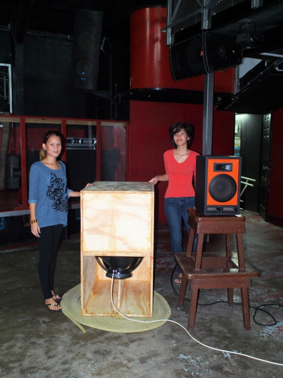
I've included a picture below showing it built but with no external finish
applied yet. Pictured next to it is one of my Blastoramas, which should give
a good idea of the POC4's size.
Results
Here are the measured results, which I
think are not too bad at all. If the POC4 is only going to be used below 80
Hz (which is most likely the case), DSP might not even be required to
address the out of band peaks.
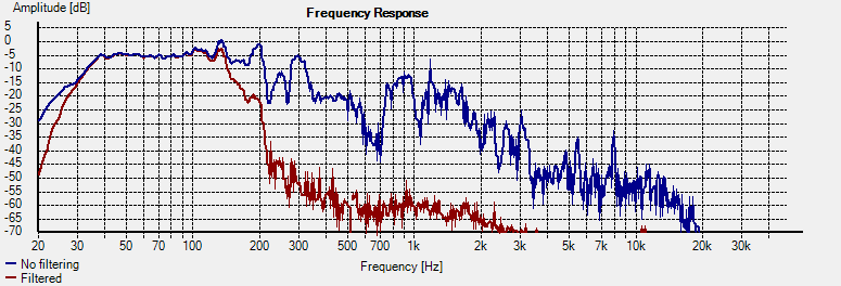
DSP
The POC4 has a 5dB peak around 130 Hz and anothe smaller one around 200
Hz. These can be corrected via DSP, but I wouldn't bother if the intent is
to use this subwoofer below 80 Hz. X-over should be 24dB/octave, with about
9ms of delay added to the top speakers.
Other Notes
Unlike POC3, this design included some "cone compensation", which is
necessary to deal with the dip just above the passband that can be caused if
the volume of the air in the driver's cone is not taken into consideration
in the design (i.e. if Vtc is set to zero in the simulation). This
time around I made a guess at how much compensation would be required, and
it looked like my guess was a good one. For POC5, I will modify the
spreadsheet to include a more accurate representation for any cone
compensation that's required. Like POC3, this design suffers from a
bit of panel flex (the bottom panel), which can cause the box to "walk" at
high volume. Resolving this should be very easy - just double up on
the bottom panel as was done for POC3.
Related Projects
External Links